R978017748 Rexroth hydraulische richtingsklep 4WE6Y62/EG24N9K4/62 Echt nieuw
Productoverzicht
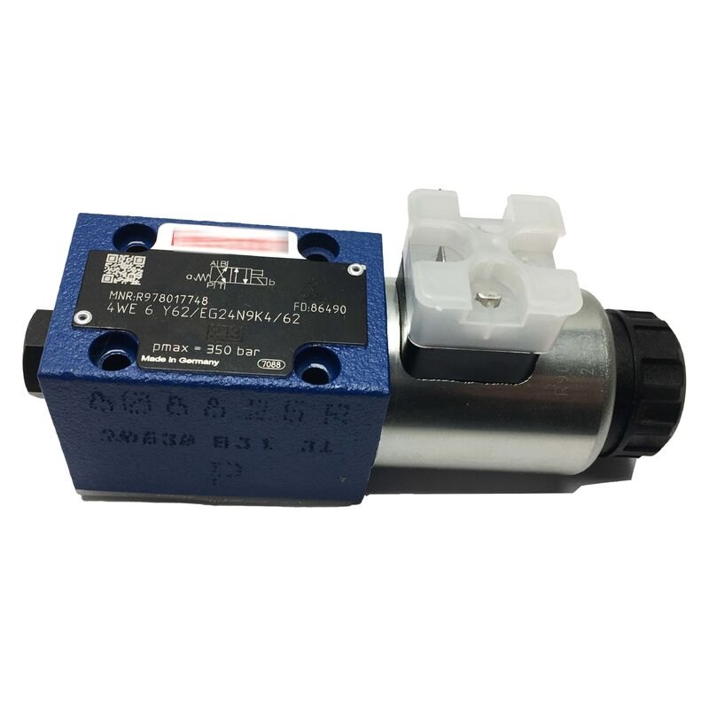
DeRexroth R978017748is een direct bediende directionele regelklep in de WE6-serie - Rexroth's meest gebruikte familie van hydraulische directionele regelkleppen voor industriële toepassingen. Bij NG6 (D03)-formaat met een enkele 24V DC-solenoïde en veerretour, is de 4WE6Y6X/EG24N9K4/62 geconfigureerd voor 4/2-wegschakeling met symbool Y-spoelgeometrie.
Het regelt de richting van de hydraulische oliestroom en het schakelen van circuits in industriële hydraulische krachtbronnen, werktuigmachines, perssystemen en productiemachines waar een 24V DC-signaal van een PLC-uitgangskaart zich rechtstreeks moet vertalen in hydraulische cilinder- of motorbeweging.
De R978017748 biedt specifiek de 4/2-weg (Y-symbool) functie, waarbij de niet-bekrachtigde toestand P met B en A met T verbindt, en de bekrachtigde toestand dit omkeert naar P met A en B met T. Deze configuratie wordt veel gebruikt waarbij een cilinder bij verlies van elektrisch vermogen naar de ene eindpositie moet gaan, met positieve activering naar de tegenovergestelde positie wanneer hij wordt opgedragen.
Met een nominaal debiet van 60 lpm en een maximale druk van 350 bar bedient de klep het volledige werkbereik van standaard industriële hydraulische circuits. Dankzij de verborgen handmatige bediening kunnen operators de klepspoel handmatig verschuiven tijdens inbedrijfstelling, foutdiagnose of machine-instellingen zonder dat er solenoïdespanning wordt toegepast.
Belangrijkste specificaties
| Parameter |
Waarde |
| Ventielcode |
4WE6Y6X/EG24N9K4/62 |
| Functie |
4/2-weg, veerretour |
| Nominale maat |
NG6 (D03) |
| Solenoïde spanning |
24 V gelijkstroom |
| Solenoïde vermogen |
30W |
| Maximale stroom |
60 LPM |
| Maximale druk |
350 bar (5.076 PSI) |
| Handmatige overschrijving |
Verborgen |
| Connector |
3-polig (EN 175301-803) |
| Montage standaard |
ISO 4401-03 / DIN 24340-A6 / CETOP R35H-03 / NFPA-D03 |
| Huisvesting |
Gietijzer |
| Zeehonden |
NBR |
| Bedrijfstemperatuur |
−15 tot +80°C |
| Gewicht |
1,44 kg |
Spoelsymbool Y — Circuitfunctie
In de WE6-naamgevingsconventie van Rexroth beschrijft de letter na "WE6" het hydraulische symbool van de spoel: de padconfiguratie in zowel de bekrachtigde als de niet-bekrachtigde toestand. Symbool Y duidt een specifieke opstelling aan die gebruikelijk is in enkelwerkende circuits en retourbewegingstoepassingen:
- Stroomloze toestand (veerteruggang, magneet uit):P → B, A → T — De hydraulische druk van de toevoer (P) wordt naar de uitgang van de B-poort geleid, terwijl de A-poort terugvloeit naar de tank (T).
- Bekrachtigde toestand (solenoïde aan):P → A, B → T — Door 24 V DC op de solenoïde aan te leggen, wordt het stroompad omgekeerd: P wordt gevoed naar A, B wordt afgevoerd naar T.
Deze Y-spoelconfiguratie wordt algemeen gespecificeerd waar de vereisten voor een faalveilige positie in lijn zijn met de richting van de veerretour - bijvoorbeeld het losmaken van gereedschap bij vermogensverlies in werktuigmachines, of het terugtrekken van de actuator als de veilige toestand in pers- en vormmachines.
D03 (NG6) Montage-interface
De NG6/D03 montage-interface is het meest gestandaardiseerde montagepatroon voor subplaat voor richtingskleppen maat 6 in de industriële hydrauliek. Hetzelfde boutpatroon, poortindeling en positie van de positioneerpen verschijnen onder vier verschillende normen: ISO 4401-03, DIN 24340-A6, CETOP R35H-03 en NFPA-D03.
Het achtervoegsel /62 op de bestelcode van de klep geeft aan dat het klephuis een pingat in de ISO 4401-positie heeft. Dit onderscheid is van belang bij het specificeren van een vervangende klep voor een bestaand spruitstuk. Controleer of op de geïnstalleerde onderplaat een paspen aanwezig is; Als dit het geval is, is het achtervoegsel /62 of een gelijkwaardig achtervoegsel vereist.
Natte pin-solenoïdeconstructie
De WE6-serie maakt gebruik van een natte-pin (in olie ondergedompelde) solenoïdeconstructie. De elektromagnetische duwstang strekt zich uit tot in de hydraulische olieomgeving van het kleplichaam, waarbij de hydraulische vloeistof zelf wordt gebruikt voor smering en koeling. Dit elimineert de afzonderlijke O-ringafdichting die nodig zou zijn voor een dry-pin-ontwerp, waardoor potentiële lekpunten worden verminderd.
Het magneetspoelsamenstel is verwijderbaar zonder de klep los te koppelen van de subplaat en zonder de hydraulische druk uit het circuit te laten ontsnappen. De spoelhuls glijdt van het solenoïdelichaam nadat de borgmoer van de spoel is losgemaakt, waardoor vervanging van de spoel ter plaatse mogelijk is - een aanzienlijk onderhoudsvoordeel in krappe spruitstukposities.
Veelgestelde vragen
Vraag 1: Het achtervoegsel van de klep is /62. Wat is de betekenis hiervan en heeft dit invloed op de compatibiliteit van subplaten?
Het achtervoegsel /62 duidt een specifieke configuratie van het plaatsingspengat aan voor de klep-naar-subplaat-interface, overeenkomend met de ISO 4401-norm met plaatsingspen. Als op uw subplaat een paspen is geïnstalleerd, moet u een klep gebruiken met het bijbehorende achtervoegsel voor het pasgat. Als de configuratie van de positioneerpennen niet goed past, zal de klep niet correct tegen het oppervlak van de subplaat aanliggen, wat kan leiden tot schade aan de afdichting en externe lekkage.
Q2: Deze klep heeft een verborgen handmatige bediening. Hoe wordt het bediend?
De verborgen handbediening is een verzonken punaise-actuator op het solenoïde-uiteinde van het klephuis, toegankelijk met behulp van een klein gereedschap (doorgaans een inbussleutel van 3 mm of een speciaal gereedschap voor overschrijving). Door de pin handmatig naar binnen te drukken, verschuift de spoel, waardoor de bediening van de solenoïde wordt gerepliceerd zonder elektrische stroom op de spoel toe te passen. Het verborgen ontwerp voorkomt onbedoelde handmatige bediening tijdens normaal gebruik.
Vraag 3: De maximale stroom wordt vermeld als 60 LPM. Kan de klep hogere transiënte stromen aan zonder schade?
Het vermogen van 60 LPM is het maximale continue bedrijfsdebiet, en niet een absolute schadedrempel. Korte voorbijgaande stromen boven 60 LPM worden over het algemeen zonder schade getolereerd. Aanhoudende stromingen die aanzienlijk boven deze waarde liggen, verhogen echter de hydraulische krachten op de spoel, waardoor een grotere drukval, hogere temperaturen en versnelde interne slijtage ontstaan. Voor circuits die regelmatig boven de 60 LPM werken, moet een grotere klepgrootte worden gespecificeerd.
Vraag 4: Welke hydraulische vloeistoffen zijn compatibel met de NBR-afdichtingen van deze klep?
NBR-afdichtingen (nitril-butadieenrubber) zijn compatibel met standaard hydraulische oliën op minerale basis (ISO VG 46 en ISO VG 68 zijn de meest voorkomende). NBR-afdichtingen zijn niet compatibel met fosfaatester (brandwerende) vloeistoffen, polyolestervloeistoffen of water-glycolmengsels. Voor systemen die brandwerende vloeistoffen gebruiken, biedt Rexroth WE6-varianten met FKM (Viton) afdichtingsspecificaties.
Q5: De solenoïde heeft een vermogen van 30 W en 24 V DC. Welke bescherming heeft de spoel tegen spanningspieken?
De spoelspecificatie /EG24N9K4 duidt op een spoel die is ontworpen met een geïntegreerde onderdrukkingsdiode (het "K4"-element) voor de 24V DC-voeding. Wanneer de PLC-uitgang de solenoïde uitschakelt, genereert het instortende magnetische veld een tegen-EMF-spanningspiek. De geïntegreerde suppressordiode klemt deze piek op een veilig niveau en beschermt de PLC-uitgangstransistor en de omliggende elektronica.


 Uw bericht moet tussen de 20-3.000 tekens bevatten!